Circuit explanation
of Inverting converter
(MC34063A)
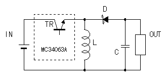 The circuit on the left is the basic circuit of the inverting converter. The position of the coil and the diode is different from the step down. The circuit on the left is the basic circuit of the inverting converter. The position of the coil and the diode is different from the step down.The input electric power is sent to the output circuit by the switching operation of the regulator. The coil of the output circuit stores up the input electric power when TR is ON. Then, it slips the electrical energy which was stored up when TR was OFF to the output and it supplies the load with the electric power. The capacitor of the output circuit does the supply of electric power to the load in the leveling like the coil. The negative potential occurs when slipping the electrical energy which was stored up at the coil to the load. 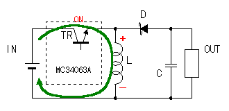 When TR is ON, the input electric power is supplied to the coil (L1). At this time, the electrical energy is stored up at the coil (L1). In this condition, the side of the output of the coil becomes positive and the side of the grounding becomes the negative potential. When TR is ON, the input electric power is supplied to the coil (L1). At this time, the electrical energy is stored up at the coil (L1). In this condition, the side of the output of the coil becomes positive and the side of the grounding becomes the negative potential.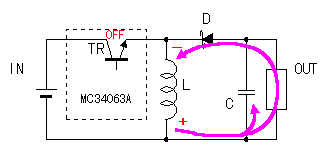 When TR becomes OFF, the coil slips the electrical energy which was stored up by trying to continue to pass the electric current.(Lenz's law) In this condition, the side of the output of the coil becomes negative and the side of the grounding becomes the positive potential. It becomes such potential because it tries to continue to pass the electric current. The electrical energy which was stored up at the coil is supplied through the load and the diode. When there is not a diode, the electrical energy which was stored up at the coil can not be supplied. At this time, the electrical energy which was stored up at the capacitor is supplied to the load too. When TR becomes OFF, the coil slips the electrical energy which was stored up by trying to continue to pass the electric current.(Lenz's law) In this condition, the side of the output of the coil becomes negative and the side of the grounding becomes the positive potential. It becomes such potential because it tries to continue to pass the electric current. The electrical energy which was stored up at the coil is supplied through the load and the diode. When there is not a diode, the electrical energy which was stored up at the coil can not be supplied. At this time, the electrical energy which was stored up at the capacitor is supplied to the load too.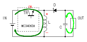 The input electric power is again applied through TR when TR becomes ON. The positive input electric power has been supplied to the load when the countercurrent with the diode isn't prevented when TR becomes ON. It decreases the negative electric power which occurred with the coil. Because it is, the diode must be used the the shottky barrier diode or the first recovery diode. The input electric power is again applied through TR when TR becomes ON. The positive input electric power has been supplied to the load when the countercurrent with the diode isn't prevented when TR becomes ON. It decreases the negative electric power which occurred with the coil. Because it is, the diode must be used the the shottky barrier diode or the first recovery diode.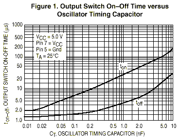 The figure on the left is the chart which shows the relation between the timing capacitor and the switching time which is mentioned to the data sheet. The figure on the left is the chart which shows the relation between the timing capacitor and the switching time which is mentioned to the data sheet.The circuit which was made this time used the 1500-pF capacitor. In this case, it becomes ton=40µS, toff=5µS. Because it is, the frequency is f = 1/(ton+toff) = 22kHz. I used the value which is mentioned to the sample circuit of the data sheet as the value of the capacitor. I think that the high frequency can do the coil and so on smaller. However, because the high-speed switching made the loss of the switching transistor and the diode big, I used the value of the data sheet. The main coil (L1) is preparatory to pass the electric current continuously to the load when TR becomes OFF. The output power with the stable one with the bigger inductance value can be gotten. However, in case of the big inductance value, the high voltage occurs in the both edges of the coil when TR is OFF. As for this voltage, the leveling is done with the capacitor on the side of the output but the ripple increases when the coil is big. I could not understand the calculation formula which finds the inductance value which is mentioned to the data sheet. So, I used the inductance which is near the value of the sample circuit. L(min) = ((Vin(min) - Vsat) / Ipk(switch) ) x ton(max)
There is an effect in the value of the capacitor in the bigger one. You must consider the use because the size of the capacitor with the big capacity is big and the many inflow electric currents occur. Because the big charging and discharge electric current flows through this capacitor, you use the small one of the ESR(Equivalent Series Resistance). There is a way of connecting the capacitor in parallel as the means of making the ESR small. 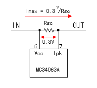 MC34063A can prevent the destruction by the over-current by detecting the input electric current. MC34063A can prevent the destruction by the over-current by detecting the input electric current.The over-current is detected by the voltage drop of the resistance which is put in the input circuit in series. The regulator judges the over-current when the voltage difference between Vcc and the over-current detection terminal(Ipk) is more than 0.3 V and limits the supply of electric power to the output. Because I used the 0.22-ohm resistor at the circuit this time, as the input current limiting value, it becomes 0.3V / 0.22ohm = 1.36A. I make the connection between the side of the output of R1 and the 7th pin of the regulator the independent pattern on the printed board. This is to more correctly detect the voltage which is applied to R1. The sheet copper of the printed board is small but has the resistance value. When few electric currents occur, the voltage drop with the printed board can be ignored. Because the over-current detection detects the voltage of the milli-volt, when the electric current is big, the voltage drop of the printed board can not be ignored. I connect the pattern with the side of the output of R1 directly and prevent the influence of the big electric current which flows through the printed wiring. 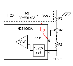 MC34063A compares the reference voltage of 1.25-V and the output voltage and is controlling the output voltage to be constant. In case of inverting converter, the reference voltage grounding terminal of the regulator connects with the side of the negative output. Because it is, it is different from the case of the step down and the variable resistor for the output voltage adjustment connects with the side of the grounding. The output voltage can be calculated by the following formula.
Vout = ((R2+VR1+R3)/R2)x1.25
At the circuit this time, R2 = 1.5k-ohm, R3 = 1k-ohm, VR1 = 10k-ohm, it changes as follows in the output voltage by the change of VR1.
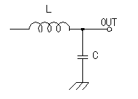 As for the switching regulator, the switching frequency ripple appears in the output. You can make the ripple little in making the capacitor (C2) which connects with the output big. I prepare another ripple filter for the output with the circuit this time and make the ripple little. As for the switching regulator, the switching frequency ripple appears in the output. You can make the ripple little in making the capacitor (C2) which connects with the output big. I prepare another ripple filter for the output with the circuit this time and make the ripple little.The sample circuit of the data sheet is using the 1µH one as the coil. I used the 25µH one. Because, I could not acquire the coil of 1µH, 2A. When the inductance value is big, the filter is effective but the efficiency rather falls. The toroidal coil can be made by yourself, too. |