 The change of the voltage and the current by the load change The change of the voltage and the current by the load change

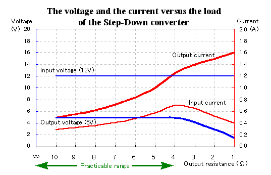
When making the load resistance which connects with the output small, there is a point where the output voltage begins to fall. At the circuit which was made this time, the output voltage begins to fall at less than 4-ohm in the load resistance. I think that this is the one by the limitation on the input electric current(In the calculation, it is 1.3-A).
In the graph, the peak of the input electric current is about 0.7-A. However, the ammeter can not measure the electric current value to flow through like the pulse. When the transistor of the regulator is in the ON condition, more than 1-A electric current should be flowing. The reason for the fall of the output voltage seems to be limited by this electric current value.
The output current is increasing when the resistance value is less than 4-ohm. However, as shown in the graph below, the output power in this case is decreasing. Because it is, the input electric current is decreasing. |

 The electric power change by the load change The electric power change by the load change

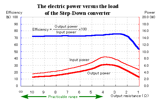
The figure above shows the change of the input/output electric power and the efficiency when making the load resistance small. In case of less than 4-ohm resistance, the output power is falling.
When the output power increases, the loss in the converter(Input power - Output power) rather increases at about 1 to 2-W. Therefore, the efficiency in the practical use range becomes about 70% of the flat change. |

 The temperature rise measurement The temperature rise measurement

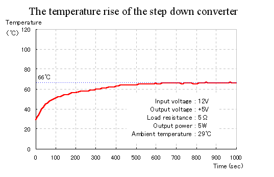
I made the thermocouple temperature sensor touch the top of the case of the regulator by the pinpoint and measured the temperature rise. I measured in the condition of 5 W that the output of the regulator is near the maximum output. The loss of the regulator is about 2 W. As a result of the measurement, within the about 10 minutes, the temperature became constant (66°C).
The radiation of the heat which occurred with the regulator is done at the case and the print pattern through the pin.
The operating junction temperature of MC34063A is +150°C. There is a margin with the temperature because the place of the measurement of the temperature is the top of the IC case and is the place which is near the junction.
I am not measuring about the step up and inverting converter. However, because the losse of the both regulators are about 2 W like step-down, I think that the temperature rise is same. |

 The ripple voltage The ripple voltage
The photograph above is the wave form of the ripple voltage which appears in the output in case of the no-load. The voltage is about 10 mVp-p. It becomes 0.2% of the ripple voltages because the output voltage is 5 V.
This ripple voltage passes away almost when the electric current flows through the load and the output voltage becomes the pure DC voltage. At the circuit this time, the secondary filter is used. I think that the filter operation of the coil (L2) of the secondary filter works when the electric current flows through the load and the flow of the ripple current is prevented. |
 |


