Parts explanation for Battery charger
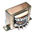 This is the transformer which changes AC100V into AC24V. 500mA type is used as a secondary side (24V). The charging current is having 100 to 200mA assumed. Therefore, I made it 500mA type in consideration of the margin. |
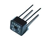 2A type is used as current capacity. Since the current to be used is 500mA at the maximum, it is satisfactory also by 1A type. |
 This regulator is used in order to control the maximum voltage of charge voltage. This regulator can make output voltage variable by a resistor. The attachment section of a regulator is connected to the output terminal. Therefore, in case it attaches in a case, the sheet for insulation is required. |
 This regulator is used in order to control the charging current. Originally, this regulator is the parts for voltage control. However, in this circuit, it is used as a circuit which makes current regularity using the property. Please look at circuit explanation for details. |
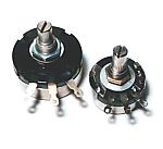 These are the variable resisters for setting up voltage and current. Since much current does not flow into the variable resister for voltage control, it is the usual thing and does not matter. The charging current flows into the variable resister for current control. Therefore, it is necessary to use a variable resister with big electric power capacity. I am using 2W type. |
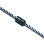 Diode is attached to the output circuit so that current may not flow backwards from a battery. I am using the type of electric strength 100V and current capacity 1A. |
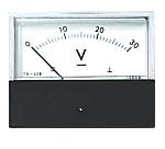 This is a voltmeter for supervising output voltage. The object for 30V is used. |
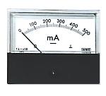 This is an ammeter for supervising the output current. The object for 500mA is used. |
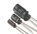 These aluminum electrolytic capacitors are used in order to control the ripple voltage generated when AC voltage is rectified and to make it fixed direct current voltage. In the case of the aluminum electrolytic capacitor, the voltage of the maximum which can be used is decided. It is necessary to use the parts of work voltage higher than the voltage of the circuit to connect. |
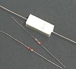 In order for the charging current to flow into R3, it is necessary to use a resistor with big electric power capacity. I am using the cement resistor of 5W type. Other resistors are satisfactory 1/4W. |
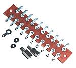 There are few electronic parts with this equipment. Moreover, there are many parts attached in a case. Therefore, how I fix parts using the terminal for wiring without using a printed circuit board is adopted. |
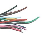 In this circuit, since big current does not flow, the wire rod of allowable-current 4A is used. |
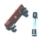 The fuse is attached for safety. The capacity of 1A is enough. |
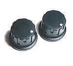 These are the knobs attached in the variable resister for adjusting voltage and current. Because adjustment is not performed frequently, it is not inconvenient even if it does not use. |
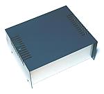 PS-3 made by LEAD company is used as the case. It is 160mm(W), 130mm(D) and 70mm(H). |
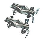 In my case, this charger is attached in the stick of the iron on the ceiling of a garage. Therefore, I formed attachment metallic ornaments in the upper part of a case. |
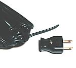 This is AC input cable of a charger. |
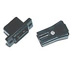 AC input cable of a charger can also wire directly into a case, without using a connector. I am using the connector in consideration of removal of a charger. |
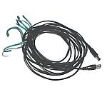 This is the cable which connects the output of a charger to the battery of a car. It is not a special cable. Please choose according to your environment. |
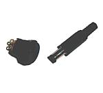 This cable may also wire a charger directly. |
 This is the back panel. The panel printed on paper is fixed with a transparent acrylics board. |
|