Build Your Own ISP Adapter for the SX 28
Today, I found the need to debug an SX-28 on a PCB where I did not provide the usual 4-pin
header for the SX-Key, and the OSC1 jumper because I never expected that it would be
necessary to debug this "bullet-proof" application, but to be honest, the main reason for not
providing the ISP feature was due to RFI and EMC reasons.
Nevertheless, I found a "quick-and-dirty" solution that I'd like to share with you.
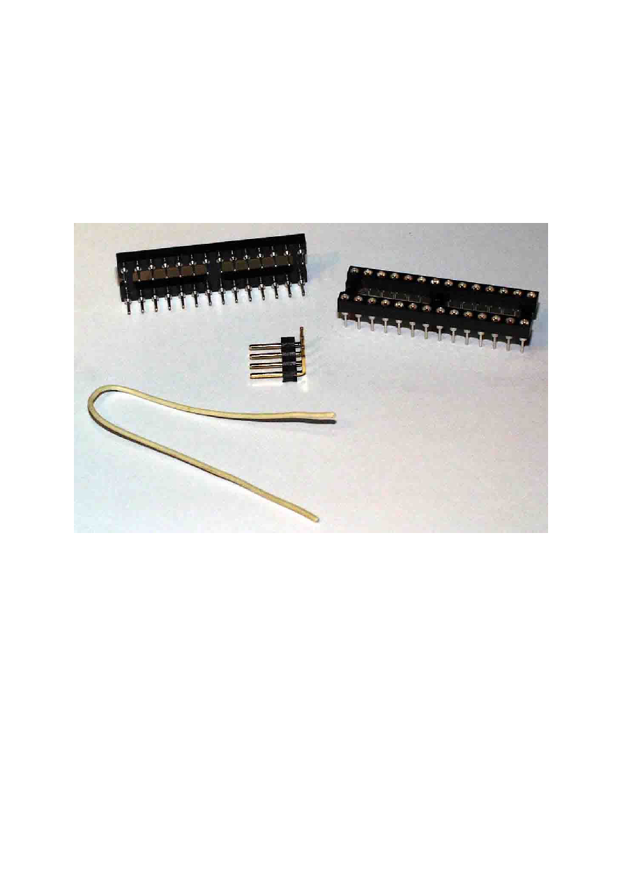
Here is what you need:
2 precision IC 28-pin sockets
1 four-pin header with one side bent to 90°, or one with four straight pins
1 short piece of isolated wire
I will call one of the 28-pin sockets the "upper", and the other one the "lower" socket from
now on.
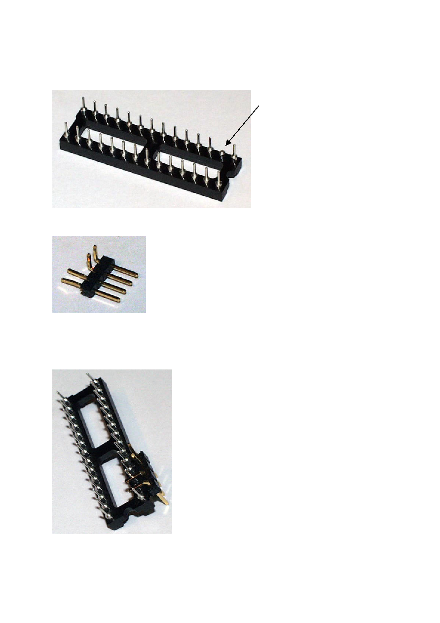
First, lets take care of the upper socket:
Cut off the small diameter pin 27 (the SX28 OSC1 pin) which makes it look like this:
Next, take care of the four-pin header, and make it look like this:
If you are using an "all-straight" header, bend the upper two pins by 90°. If you have a 90°
header, bend the lower two pins straight.
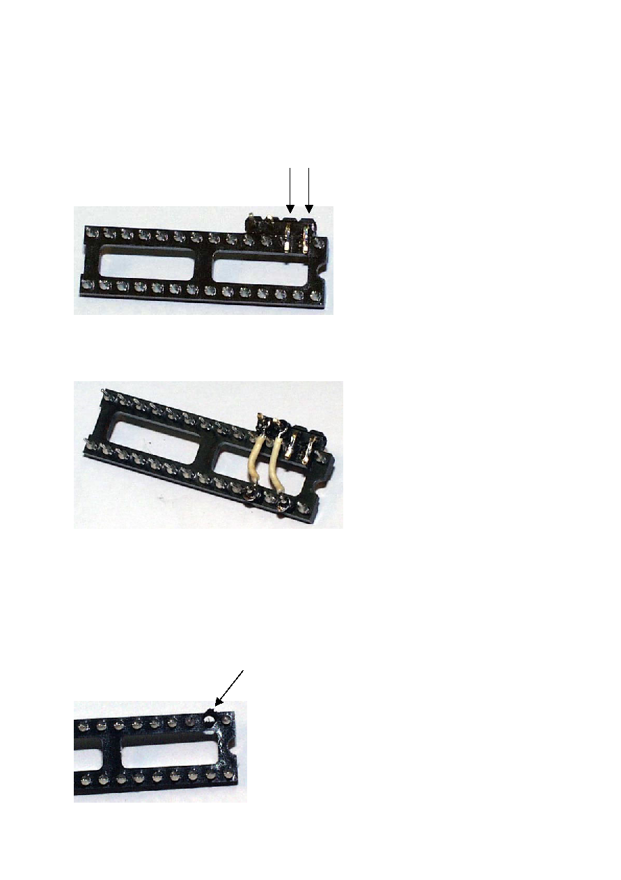
Use some drops of "Superglue" to attach the 4-pin header to the upper socket like this:
Make sure that the two bent header pins are as close as possible to the two matching socket
pins (pin 27 OSC1 and pin 26 OSC2).
From now on, you'll need to do some soldering. It is a good idea to use a tiny solder tip, and
to take care not to apply excessive heat in order to avoid that the plastic of the socket and
the header pins melts too much.
Now solder the two 90° header pins to the upper socket pins 26 and 27:
Next, we need to connect the remaining two straight header pins to the Vdd (pin 2) and Vcc
(pin 4) upper socket pins. Use two short pieces of the isolated wires to make your
"masterpiece" look like this:
Make sure that the two wires attached to pins 2 (Vdd) and 4 (Vss) of the upper socket are
located as close as possible to the plastic part of the socket without touching other socket
pins.
Next comes the "lower socket":
Remove pin 27 by attaching some heat from the soldering iron for a while, and then pull it
out. This makes the socket look like this:
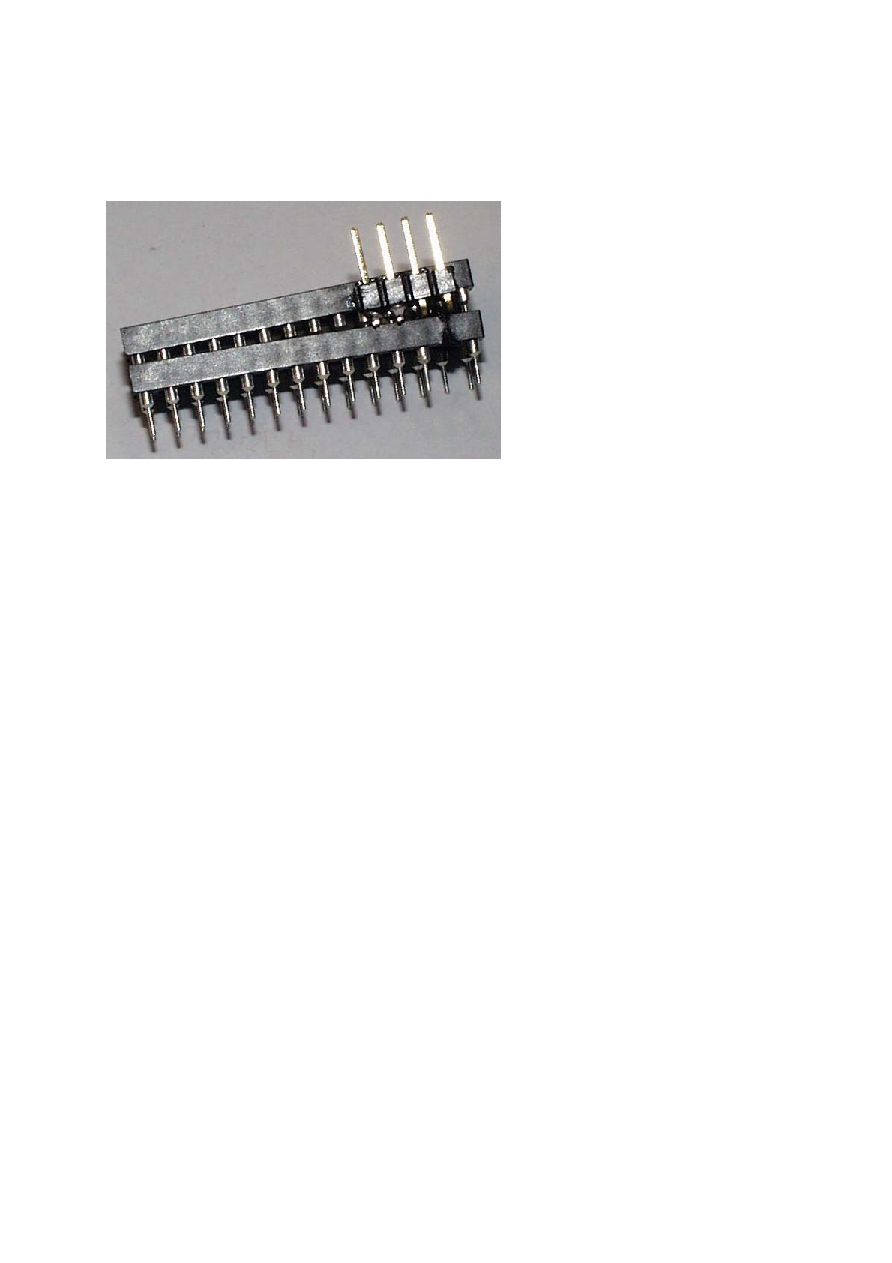
Here comes the final step:
Make sure that the notches of both sockets are aligned to the same direction, and tightly
push the upper socket into the lower socket. The final assembly should look like this:
Although this assembly looks a bit "beveled", it will work fine, as long as all pins of the upper
socket (except pin 27 OSC1) contact the lower socket's pins.
Please use an ohmmeter to verify that this is the case. Also check the four header pins. From
left to right, they should be connected to
Pin 4 of both sockets (Vss)
Pin 2 of both sockets (Vdd)
Pin 26 of both sockets (OSC2)
Pin 27 of the upper socket (SX-28 OSC1)
Also double-check, that pins 2 (Vdd) and 4 (Vss) don't contact any adjacent pins.
You are now ready to debug and program an SX-28 on a board with no ISP features.
Remove the SX-28 from the board's socket, insert it into the upper adapter socket , and
insert the lower adapter socket into the board's socket.
When connecting the SX-Key to the four-pin header, make sure that it is aligned correctly,
i.e. its OSC1 pin should be connected to the header pin that is closest to the socket's
"notches"
By the way there is a socket on your board for the SX-28, isn't it ???
Greetings,
Günther Daubach